Description
2″ 240×320 IPS SPI+RGB TFT LCD Screen
Discover the SHENZHEN TECHSTAR ELECTRONICS INCORPORATED CO., LTD SF-TC200L-8455B-N, a cutting-edge 2.0” inch circular IPS TFT LCD Display boasting a resolution of 240×320 pixels.
- Presenting a 2-inch IPS TFT LCD display.
- With a resolution of 240×320 dots, this 2-inch LCD display impresses.
- Enjoy a full viewing experience with this 2-inch TFT display, offering a generous angle range of up to 85 degrees in each direction.
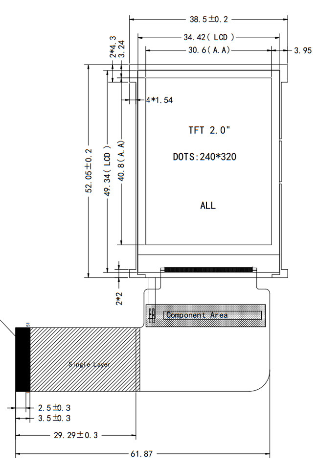
- Compact yet impactful, the dimensions of this 2-inch TFT screen measure 38.552.052.6mm.
- Featuring a built-in driver IC ILI9335, this TFT screen at 2″ stands out.
- Designed with an SPI+RGB interface, this 2-inch TFT LCD screen promises seamless integration.
- This 2-inch TFT display is devoid of a touch screen, allowing for customized CTP and RTP configurations as per requirements.
- Operating temperatures ranging from -20°C to +70°C ensure the durability of this 2-inch TFT LCD, with storage capabilities from -30°C to +80°C.
Usage
The 2.0-inch TFT LCD module finds extensive applications in various devices, including black boxes, smart wearable devices, mobile POS systems, cash readers, GPS handheld phones, handheld food ordering machines, signal analyzers, benchtop laboratory equipment, security systems, home automation, mini audio players, baby monitors, and other handheld devices.
| Product: | 2.0″ TFT LCD |
|---|---|
| Touch Screen: | Without Touch Screen(Customizable) |
| Resolution: | 240×320 Dots |
| Viewing Direction: | ALL |
| Interface: | SPI+RGB Interface |
| Pin Number: | 26 Pins |
| Connection: | ZIF type |
| Surface Luminance: | 250 Cd/m2 |
| Operating Temp.: | -20℃ To +70℃ |
| Compliance: | REACH & RoHS Compliant |
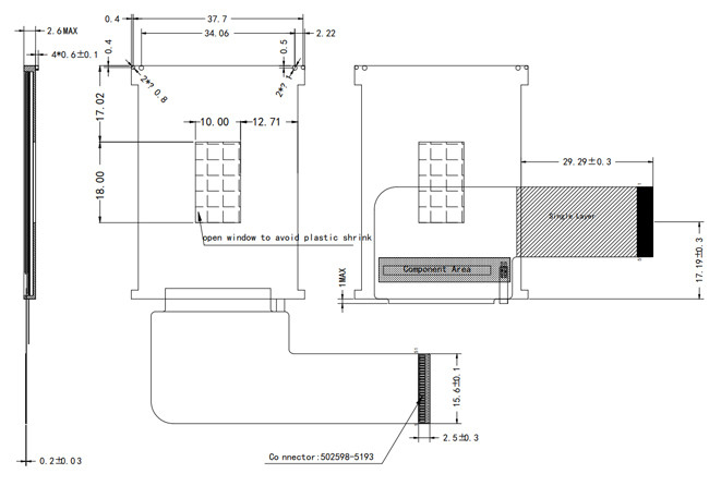
2″ inch 240×320 IPS type TFT LCD SPI+RGB interface Product Drawing
Interface Pin Definition
| NO. | PIN NAME | I/O | Description |
| 1-2 | LEDA | I | LED Anode |
| 3 | NC | – | – |
| 4-6 | LEDK | I | LED Cathode |
| 7-8 | GND | I | Ground |
| 9 | FMARK | I | Tearing effect output pin |
| 10-11 | GND | I | Ground |
| 12 | RESET | I | LCM Reset input signal |
| 13 | CS | I | Input pin for chip selection signal |
| 14 | SCL | I | SPI Clock Signal |
| 15 | VSYNC | I | Vertical Synchronizing Signal |
| 16 | HSYNC | I | Horizontal Synchronizing Signal |
| 17 | ENABLE | I | Input Data enable control |
| 18 | DOTCLK | I | Clock Signal to Sample each date |
| 19-20 | GND | I | Ground |
| 21-26 | R5-R0 | I/O | Display Data I/O (R5-R0) |
| 27-28 | GND | I | Ground |
| 29-34 | G5-G0 | I/O | Display Data I/O (G5-G0) |
| 35-36 | GND | I | Ground |
| 37-42 | B5-B0 | I/O | Display Data I/O (B5-B0) |
| 43-44 | GND | I | Ground |
| 45 | SDI | I | SPI Interface Input Pin |
| 46 | SDO | I | Read strobe signal input pin |
| 47-48 | GND | I | Ground |
| 49 | IOVCC | I | Power Supply 2.8V/1.8V Voltage |
| 50-51 | VCC | I | Power Supply 2.8V Voltage |
Maximum Absolute Limit
| Item | Symbol | Value | Unit |
| Power supply voltage for logic | VDD | 1.6~3.3 | V |
| Input voltage | Vin | VDD+0.3 | V |
| Operating temperature | Topr | -20 to 70 | °C |
| Storage temperature | Tstg | -30 to 80 | °C |
DC Characteristics (VDD=2.8V,Ta=25°C)
| Item | Symbol | Min | Type | Max | Unit | Test condition |
| Operating voltage | VDD | * | 2.8 | 3.3 | V | – |
| Supply current | IDD | – | – | 20 | mA | VDD=2.8V,Ta=25°C |
| Input voltage | VIH | 0.8VDD | – | VDD | V | – |
| VIL | 0 | – | 0.2VDD | V | ||
| Input leakage current | IIL | -1.0 | – | 1.0 | mA | VIN=VDD or VSS |
Backlight Electrical-optical Characteristics
| Item | Symbol | MIN | TYP | MAX | UNIT | Test
Condition |
| Supply Voltage | Vf | 9.2 | 9.6 | 9.8 | V | If=20 mA |
| Supply Current | If | – | 20 | – | mA | – |
| Reverse Voltage | Vr | – | – | 5 | V | – |
| Power dissipation | Pd | – | 192 | – | mW | – |
| Luminous Intensity for LCM |
– |
– | 250 | – | Cd/m2 | If=20mA |
| Uniformity for LCM | – | 80 | – | – | % | If=20 mA |
Optical Characteristics
| No. | ITEM | Symbol | Conditions | Specification | Unit | Note | |||
| Min | Typ | Max | |||||||
| 1 | Response Time | Tr+Tf | 25℃ | – | 15 | – | Ms | (1)(2) | |
| 2 | Transmittance (With PL) | T(%) | – | – | 7.1 | – | – | – | |
| 3 | Contrast Rate | Cr | θ=0,
Normal viewing angle |
– | 250 | – | – | (1)(3) | |
| 4 | Viewing
Angle
|
Hor. | θR | CR>10 | – | 80 | – | Deg | – |
| θL | – | 80 | – | ||||||
| Ver. | Θ+ | – | 80 | – | |||||
| Θ- | – | 80 | – | ||||||
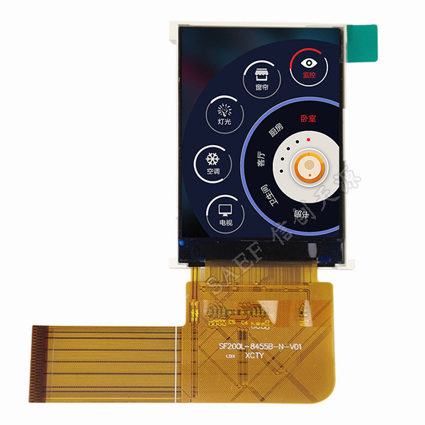
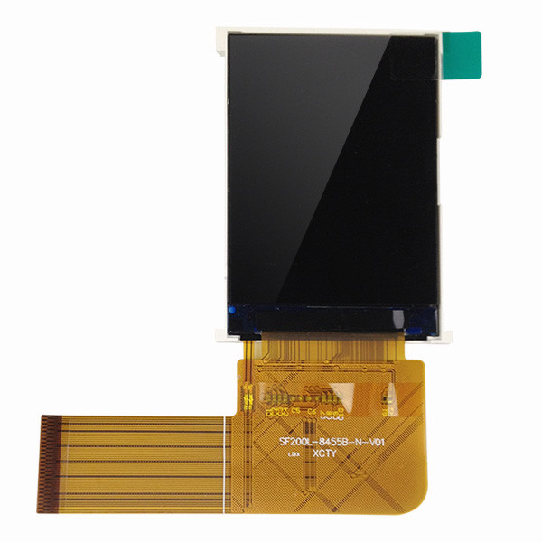
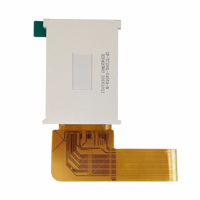
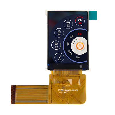
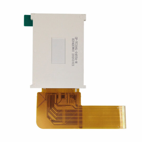
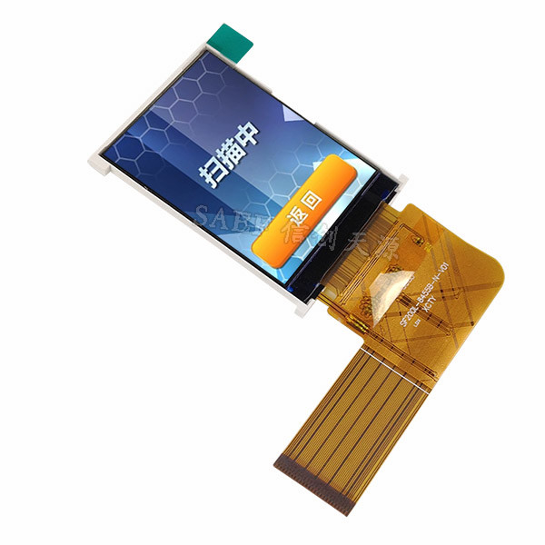
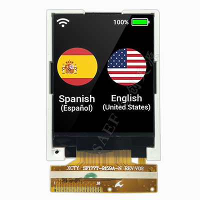
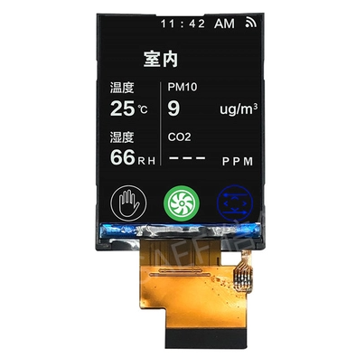
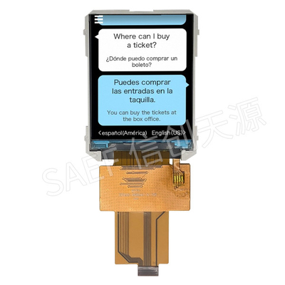
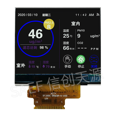
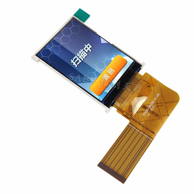
2″ inch 240×320 IPS type TFT LCD SPI+RGB interface Product Image


Reviews
There are no reviews yet.