Description
Unlocking the Potential of HT1621 Controller Segment LCD Display Module, Tailored Segment LCD Display Featuring Backlight Illumination
Exploring the Attributes of the 1621-segment LCD Screen:
- Power range: 2.4V to 5.2V
- Integration of 256KHz RC oscillator
- Option for connecting an external 32KHz chip or 256KHz frequency source
- Flexible bias options: 1/2bais or 1/3bais, with duty cycle selections including 1/2duty, 1/3duty, and 1/4duty
- Inclusion of on-chip time-base frequency source
- Versatile buzzer selection offering two frequencies
- Incorporation of built-in timebase generator and watchdog timer WDT
- Output for timebase or watchdog timer overflow
- Availability of eight time-base/watchdog timer clock sources
- Equipped with a 32segX 4com LCD driver featuring embedded 32X 4-bit display RAM memory
- Supported by a four-wire serial interface including /CS, DATA, WR, and RD (though RD is generally unused)
- Fixed on-chip LCD drive frequency set at 64Hz
- Software configurable with two command modes: data mode and command mode
- Provision of VLCD pins for adjusting LCD operating voltage to facilitate contrast adjustment
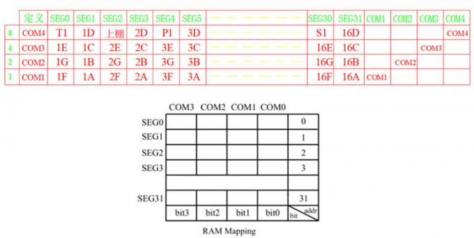
In the diagram provided, the RAM of HT1621 is illustrated, correlating with the logical table above. Understanding this is crucial.
HT1621 encompasses 32 addresses, with each address linked to 4 COM data points. For instance, inputting a 0 address lights up T1 of SGE0 at 0X08. At 0X01, the 1F light of SGE0 is activated. At 0X02, brightness 1G corresponds to SGE0. At 0X07, 1E, 1G, and 1F of SGE0 illuminate simultaneously. At 0X0F, all 1E, 1G, 1F, and T1 of SGE0 shine brightly.
Successive writing on HT1621 is possible, preferably in pairs of addresses. This facilitates table creation and simplifies writing. For instance, writing the first two addresses as 0XF7 corresponds to SGE0, SEG1, 1E, 1G, 1F, 1D, 1C, 1B, and 1A all being lit, forming a complete “8” character display.
These directives are essential for initializing the IC to enable LCD display.
Let’s delve into understanding instructions and data. 1 0 0 C8 C7 C6 C5 C4 C3 C2 C1 C0 The initial three digits of 100 signify the flag bits for instructions, with the following 9 bits indicating the instruction values. 1 0 1 C7 C6 C5 C4 C3 C2 C1 C0 The initial three digits 101 represent the flag bits for data, with the subsequent 8 bits denoting the data. Hence, observing the initial three digits of 100 signifies an instruction, while 101 indicates data.
LCD logical table correspondence
| Product: | HT1621 Controller Segment LCD |
|---|---|
| Driving Condition: | 1/8 Duty Or Customizable |
| Optics: | 6:00 or cusotmizable |
| Size: | Customizable |
| Operating Temp: | -30°C To +80°C |
| Connection: | Metal Pin Connection |
| Response Time: | 0.1 mS |
| Display Mode: | Positive / Negative, Transflective/Reflective |
| Operating Voltage: | 3.0 V |
| Display Type: | Transflective / Reflective / Transmissive |
| Backlight: | White / Amber / Blue / Yellow |
| Storage Temp.: | -35°C To +85°C |
| Dot Space: | 0.1 mm |
| Compliance: | REACH & RoHS Compliant |
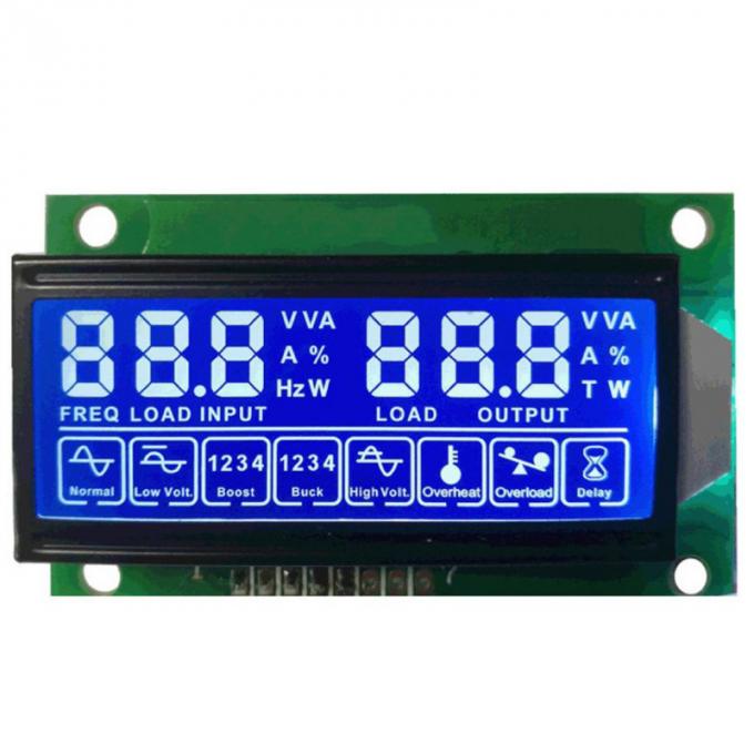
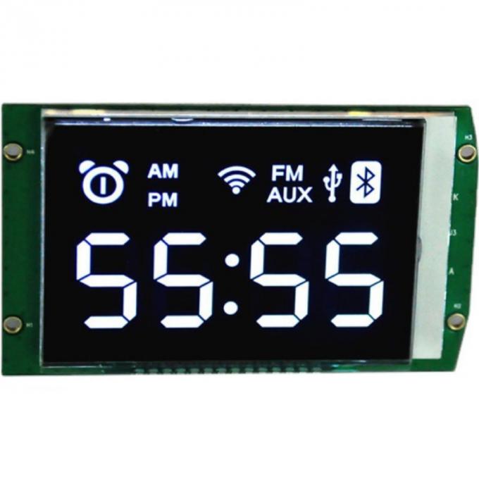
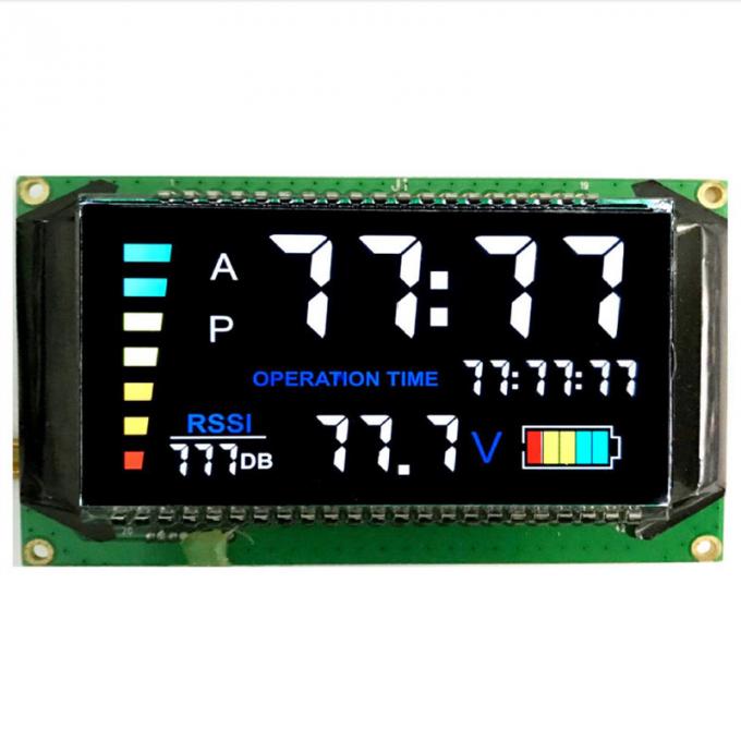
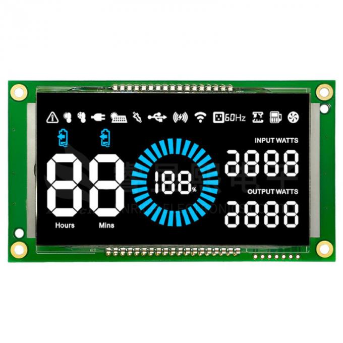
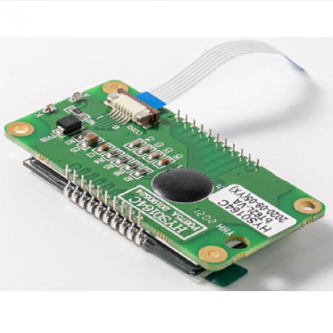
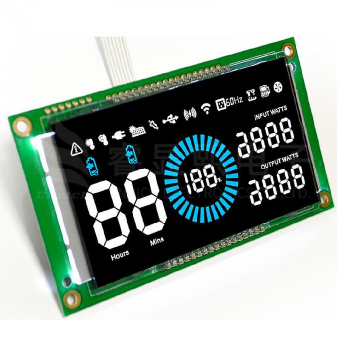
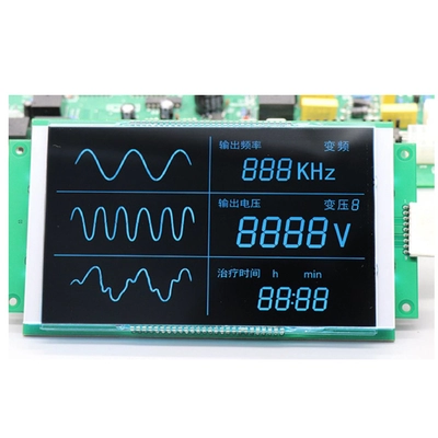
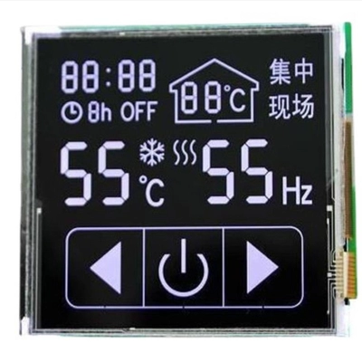
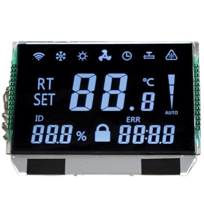
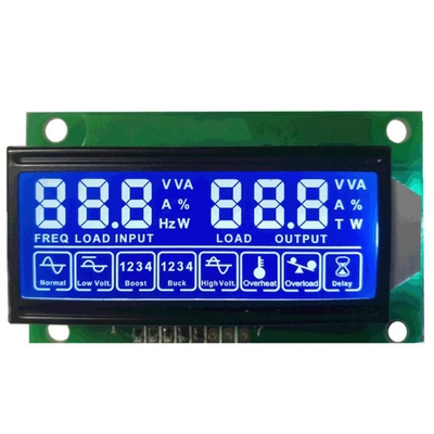
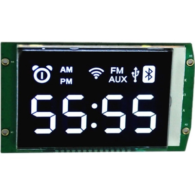
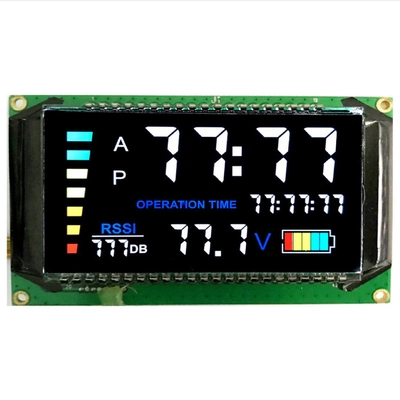
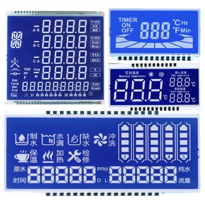
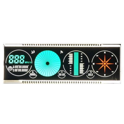
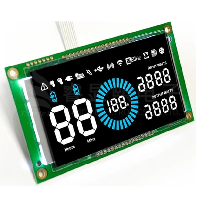
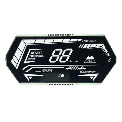
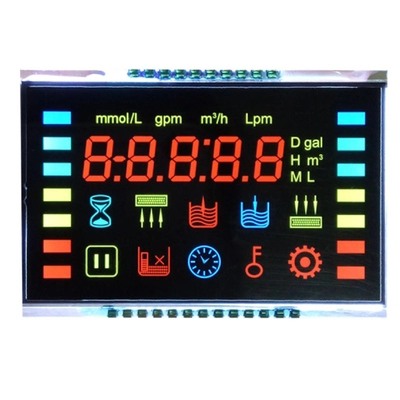
Custom VATN Negative Segment LCD Display Product Images

Reviews
There are no reviews yet.