Description
Product Spotlight: ShenZhen Techstar Electronics Incorporated Co., Ltd SFEPD213H-7004A01 E-Ink Display
Upgrade your Electronic Shelf Labels (ESLs) with this crisp, power-efficient display
Quick Overview
The ShenZhen Techstar Electronics Incorporated Co., Ltd SFEPD213H-7004A01 is a 2.13-inch Active Matrix Electrophoretic Display (EPD, or e-ink) ideal for ESL systems. It offers exceptional readability, bi-stable operation (image persists without power), and incredibly low power consumption.
Key Features
- Superb Visibility: 122×250 pixel resolution, high contrast, wide viewing angle.
- Energy Efficient: Ultra-low power usage and deep sleep mode.
- Versatile: Landscape and portrait modes.
- Easy Integration: SPI interface, on-chip temperature sensor, oscillator, booster, and regulator.
- Durable: Antiglare, commercial temperature range.
Benefits
- Clear Pricing & Promotions: Update information instantly, ensuring accuracy.
- Extended Battery Life: ESLs last longer between charges.
- Readable from Any Angle: Attract more customer attention to your shelves.
- Streamlined Operations: Reduce labor costs associated with manual price changes.
The Perfect Choice for:
- Supermarkets and grocery stores
- Retail chains
- Warehouses and logistics centers
- Any application requiring clear, dynamic pricing or product information displays
Learn more and contact ShenZhen Techstar Electronics Incorporated Co., Ltd to transform your shelf labeling!
| Screen Size | 2.13 inch | ||
|---|---|---|---|
| Display Mode | Active Matrix EPD | ||
| Display Resolution | 122(H)×250(V) Pixels | ||
| Active Area | 23.7 (H) × 28.55 (V) mm | ||
| Pixel Pitch | 0.181(H) × 0.181(V) | ||
| Pixel Configuration | Rectangle | ||
| Outline Dim.: | 29.2(H) × 59.2(V ×1.14(D) mm | ||
| Weight | 4.1 g | ||
| Logic supply voltage | 3.0V typical | ||
| Operation Temperature | 0°C to +50°C | ||
| Storage Temperature | -25°C to +60°C | ||
| Interface: | SPI | ||
| Compliance: | REACH & RoHS Compliant | ||
ESL Display 2.13 inch, EPD 2.13 inch Screen Product Drawing

Interface Pin Definition
| No. | Signal | Type | Connected to | Function |
| 1 | NC | – | – | Not connected |
| 2 | GDR | O | Power MOSFET Driver control | This pin is the N-Channel MOSFET Gate Drive Control. |
| 3 | RESE | I | Booster Control Input | This pin is the Current Sense Input for the Control Loop. |
| 4 | NC | – | – | Not connected |
| 5 | VSHR | C | Capacitor | This pin is the Positive Gate driving voltage and the Power Supply pin for VSH2, A stabilizing capacitor should be connected between VSH2 and GND. |
| 6 | TSCL(NC) | – | – | – |
| 7 | TSDA(NC) | – | – | – |
| 8 | BS | I | VSS | This pin is setting panel interface. |
| 9 | BUSY | O | Device Busy Signal | This pin is Busy state output pin. When Busy is High, the operation of the chip should not be interrupted, and Command should not be sent. |
| 10 | RES_N | I | System Reset | This pin is reset signal input. Active Low. |
| 11 | D/C | I | VDDIO or VSS | This pin is Data/Command control |
| 12 | CSB | I | VDDIO or VSS | This pin is the chip select. |
| 13 | SCL | I | Data Bus | Serial communication clock input. |
| 14 | SDA | I | Data Bus | Serial communication data input/output. |
| 15 | VDDIO | P | Power Supply | Power for interface logic pins& I/O. It should be connected with VCI. |
| 16 | VCI | P | Power Supply | Power Supply for the chip. |
| 17 | GND | P | Ground | Ground |
| 18 | VDDD | C | Capacitor | Internal regulator output, A capacitor should be connected between VDD and GND. |
| 19 | VPP(NC) | – | – | – |
|
20 |
VSH |
C |
Capacitor |
This pin is the Positive Source driving voltage.
A stabilizing capacitor should be connected between VSH and GND. |
| 21 | VGH | C | Capacitor | A stabilizing capacitor should be connected between VGH and GND. |
|
22 |
VSL |
C |
Capacitor |
This pin is the Negative Source driving voltage and the Power Supply pin for VCOM.
A stabilizing capacitor should be connected between VSL and GND. |
| 23 | VGL | C | Capacitor | A stabilizing capacitor should be connected between VGL and GND. |
|
24 |
VCOM |
C |
Capacitor |
This pin is the VCOM driving voltage A stabilizing capacitor should be connected between VCOM and GND. |
Absolute Ratings of Environment
|
Item |
Symbol |
Value |
Unit |
Note |
|
| Min. | Max. | ||||
| Storage Temperature | TST | -20 | +60 | ºC | (1),(3),(4) |
| Storage Humidity | HST | 40 | 70 | %RH | (1),(3),(4) |
| Operating Ambient Temperature | TOP | 0 | +40 | ºC | (1),(2),(3),(4) |
| Operating Ambient Humidity | HOP | 40 | 70 | %RH | (1),(2),(3),(4) |
Note (1): (a)70 %RH Max. (Ta ≦ 40 ºC), 40%RH Min. (Ta ≦ 60 ºC) where Ta is ambient temperature.
(b) No condensation and no frost in absolute ratings of Environment.
Note (2): The temperature of panel display surface area should be 0ºC Min. and 40ºC Max. Refresh time depends onoperating temperature.
Note (3): Reddish on the edge of black image is normal at high temperature.
Note (4): E Ink Material is Moisture and UV sensitive. The absolute rating operating environments describes the boundary conditions for updating the display while the absolute rating storage environment describe the boundary conditions for a display not updating. While displays are rated to perform according to specification for the warranty period at the absolute specified operating environment, the better the storage condition, the better the E Ink displays will perform. Similar to other moisture and UV sensitive components, we recommend that our displays be stored in temperature and humidity control environments, and whenever possible, under above defined Optimal Storage Condition, away from sunlight, to optimize their performance.
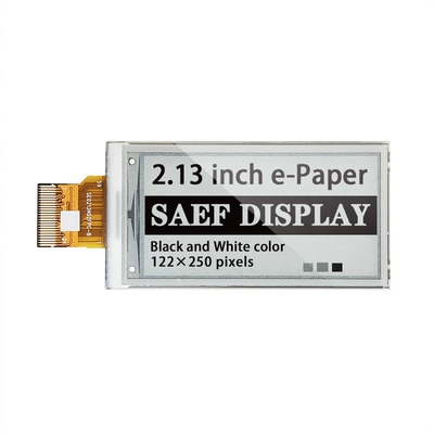
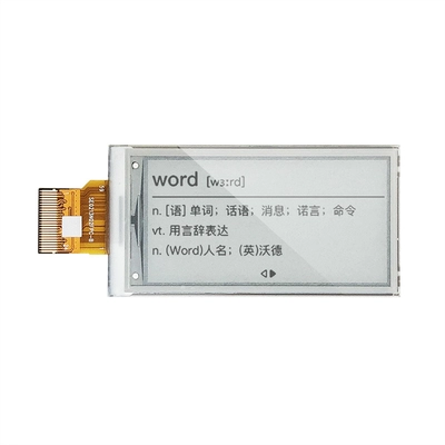
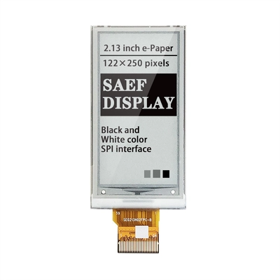
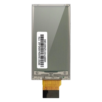
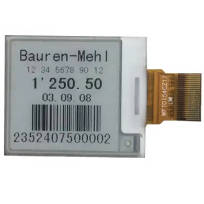
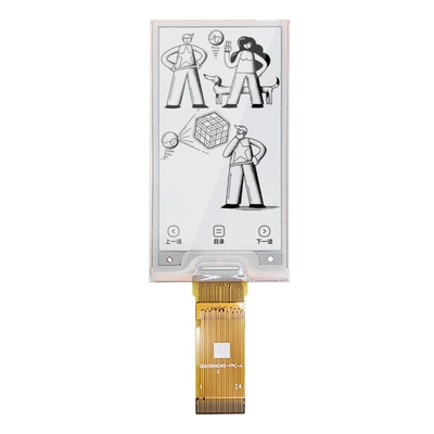
ESL Display 2.13 inch, EPD 2.13-inch Screen Product Image





Reviews
There are no reviews yet.